Features
TetGen generates the Delaunay tetrahedralization, Voronoi diagram, and convex hull for three-dimensional point sets, generates the constrained Delaunay tetrahedralizations and quality tetrahedral meshes for three-dimensional domains with piecewise linear boundary. This page illustrates some main features of TetGen.
Languages, platforms, and performance
TetGen is written in ANSI C++. The code is highly portable - it should be very easy to compile and run on all major computer systems (e.g., Unix/Linux, Windows, MacOS, etc.).
TetGen implements the randomized incremental flip algorithm of Edelsbrunner and Shah for Delaunay triangulation and convex hull.
The robustness of TetGen is enhanced by using Jonathan Shewchuk's fast and robust predicates to perform two important geometric tests - orientation test and insphere test. It is essentially a fast implementation of arbitrary precision floating-point arithmetic for fixed precision floating-point numbers. Hence, the roundoff error is avoided and the geometric tests are consistent.
Delaunay tetrahedralizations, Voronoi diagrams
For a set of 3D points, TetGen computes its exact Delaunay
tetrahedralization and its dual Voronoi diagram. The following
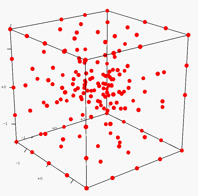
pictures show a set of 164 points sampled in a cube
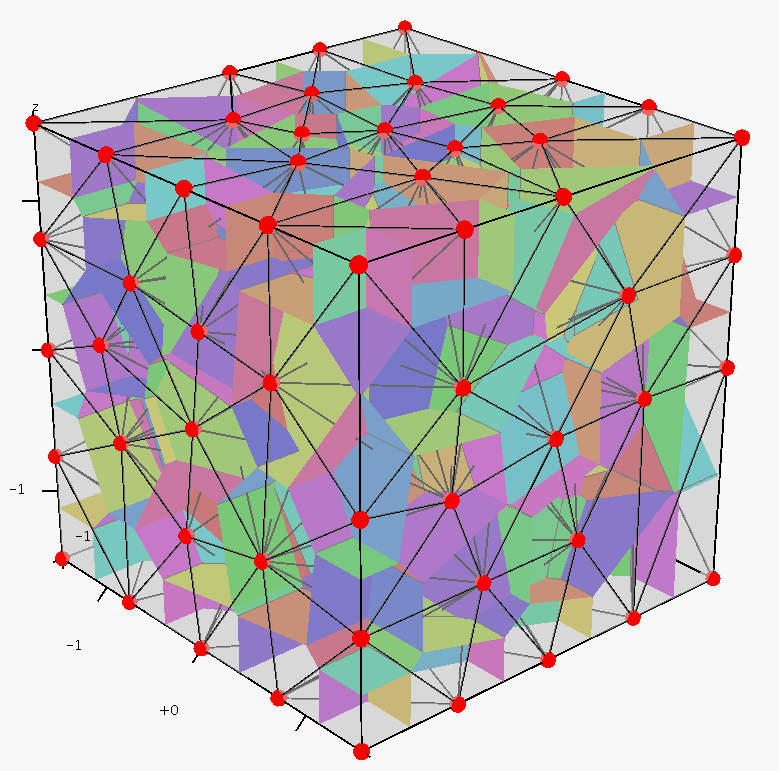
(left), the Delaunay tetrahedralization and its dual Voronoi
diagram (middle), the Voronoi faces are randomly colored for
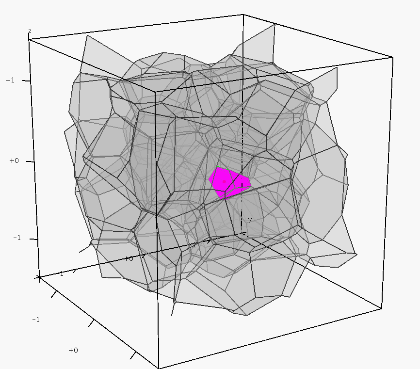
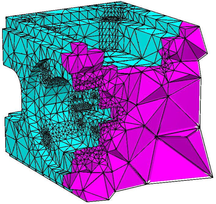
visualization, and the bounded Voronoi cells (right), an internal Voronoi cell is highlighed.
Constrained Delaunay and conforming Delaunay tetrahedralizations
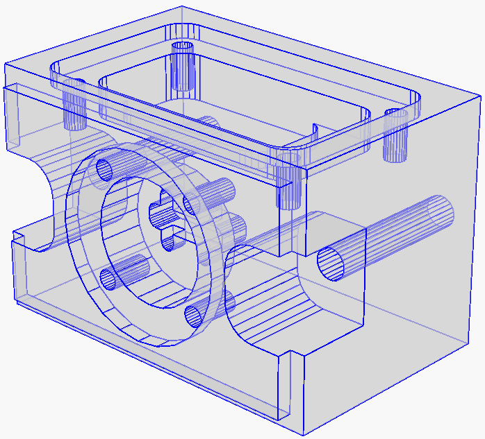
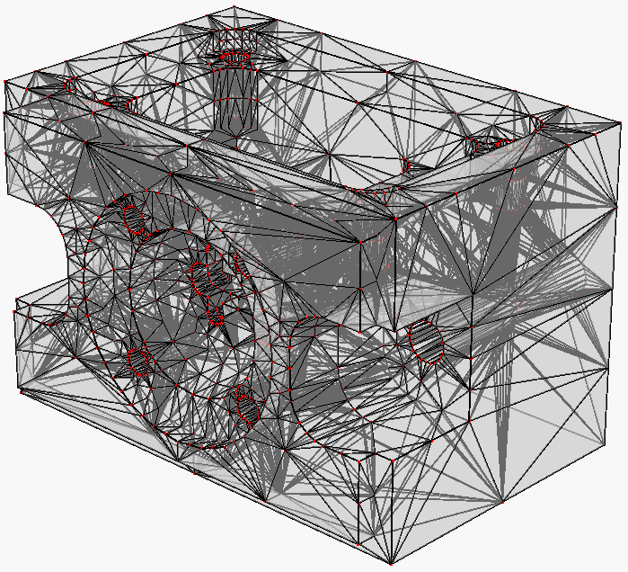
For any piecewise linear boundary (such as a surface mesh) of a 3D domain. TetGen generates a tetrahedral mesh which covers the interior of the domain and preserves the domain boundary. By default TetGen may add few additional points on the boundary so that the resulting mesh is a so-called constrained Delaunay tetrahedralization which inherites many optimal properties from the Delaunay tetrahedralization and is useful in applications like interpolation, solid modeling, etc. Alternatively, TetGen can enforce the output boundary to be identical to the input boundary. This option could be useful -- for example, to combine two meshes which share the same boundary. The following two pictures respectively illustrate an input - a piecewise linear complex (left), and its constrained Delaunay tetrahedralization (right).
Boundary conforming Delaunay meshes
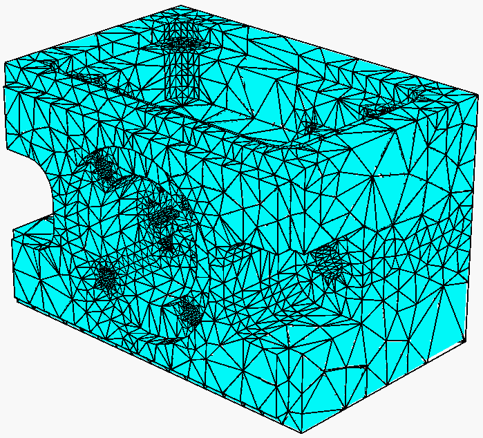
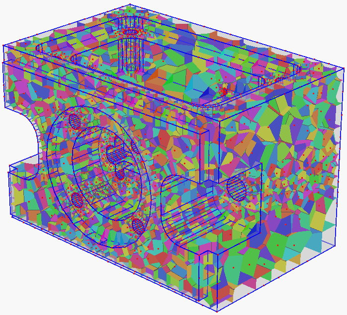
If the input boundary contains no acute angle (in practice, this condition can be relaxed to no input angle smaller than 60 degree), TetGen will generate a boundary conforming Delaunay mesh. The dual Voronoi diagram have all its vertices lie inside the domain. It is a desired finite volume partition for many applications. The following two pictures show a boundary conforming Delaunay mesh (left) and its dual - a Voronoi diagram (right).
Mesh quality, mesh size control
In numerical simulation, the mesh shape and mesh size are important for the approximation error and convergence of the numerical methods. TetGen performs efficient mesh refinement (inserting new vertices) to improve the overall mesh quality. The resulting tetrahedral mesh is a finite element mesh which consists of good-shaped tetrahedra and the mesh size well conforms to the boundary size or a user-defined smoothing size function.
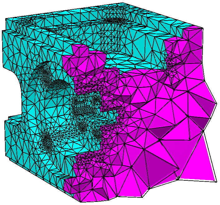
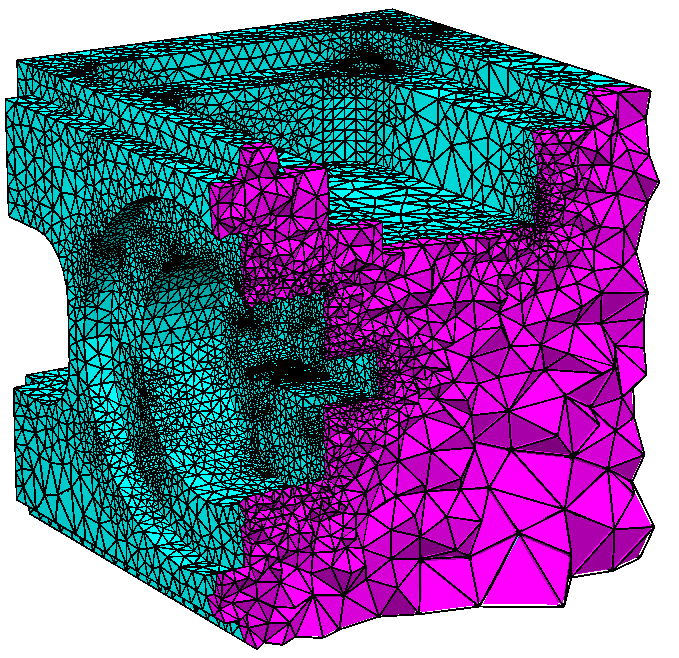
The following three meshes are generated by the mesh refinement option '-q'. From left to right, the options are '-q', '-q1.4', and '-q1.1', respectively. The number after '-q' is a parameter - the radius-edge ratio of tetrahedron, default is 2.0. The smaller the radius-edge ratio is, the better mesh quality will achieve. The sizes of the meshes are well-graded with respect to the input boundary.
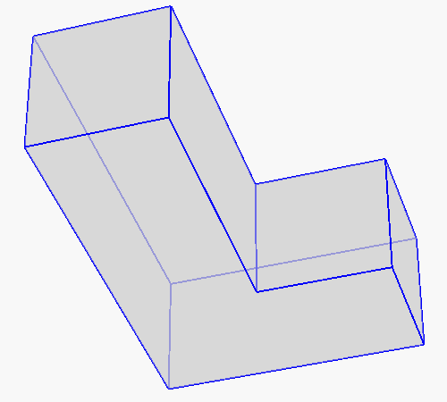
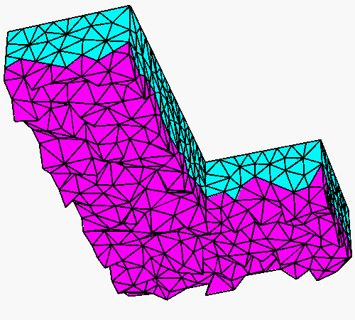
TetGen provides flexible options for mesh refinement. The following examples show two useful options. The input is a L-shaped polyhedron (Left). The middle mesh is generated by option '-q -a0.01', the -a option imposes a tetrahedron volume constraint (here is 0.01), no result tetrahedron has volume larger than it. The result mesh is uniformly sized. TetGen has various options to obtain non-uniformed sized meshes, the mesh shown in the right is generated by supplying a nodal size map (saved in L.mtr file) and the '-q -m' option, the -m option tells TetGen to read the size map.
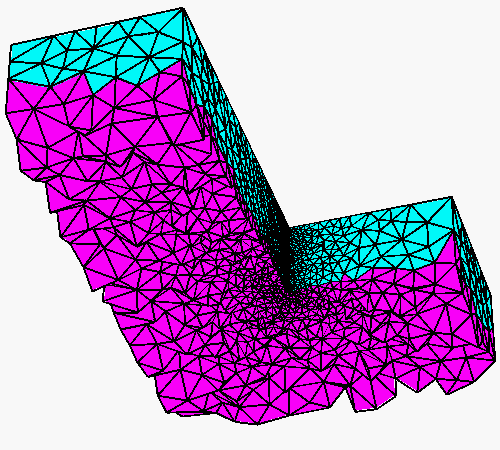
By adding a '-V' option in the command line, TetGen will print the mesh quality statistics after meshing. It looks like the follows. The mesh quality is reported in three quality measures, the "tetrahedron aspect ratio", "triangular face angle", and "tetrahedron dihedral angle". Each quality measure has a histogram.
Mesh quality statistics:

  Smallest volume:        0.0005819   |  Largest volume:         0.010872
  Shortest edge:             0.1851   |  Longest edge:             0.6305
  Smallest facangle:          20.89   |  Largest facangle:       123.9798
  Smallest dihedral:         8.2928   |  Largest dihedral:       164.8949

  Aspect ratio histogram:
         < 1.5       :       263      |      6 - 10         :        66
     1.5 - 2         :      2381      |     10 - 15         :         4
       2 - 2.5       :      2115      |     15 - 25         :         0
     2.5 - 3         :       789      |     25 - 50         :         0
       3 - 4         :       393      |     50 - 100        :         0
       4 - 6         :       180      |    100 -            :         0
  (A tetrahedron's aspect ratio is its longest edge length divided by its
    smallest side height)

  Face angle histogram:
      0 -  10 degrees:         0      |     90 - 100 degrees:      1511
     10 -  20 degrees:         0      |    100 - 110 degrees:       429
     20 -  30 degrees:       263      |    110 - 120 degrees:        61
     30 -  40 degrees:      3027      |    120 - 130 degrees:         6
     40 -  50 degrees:      6438      |    130 - 140 degrees:         0
     50 -  60 degrees:      3420      |    140 - 150 degrees:         0
     60 -  70 degrees:      2974      |    150 - 160 degrees:         0
     70 -  80 degrees:      4813      |    160 - 170 degrees:         0
     80 -  90 degrees:      3354      |    170 - 180 degrees:         0
  Minimum input face angle is 90 (degree).

  Dihedral angle histogram:
       0 -  5 degrees:         0      |     80 - 110 degrees:      4116
       5 - 10 degrees:        11      |    110 - 120 degrees:       782
      10 - 20 degrees:       181      |    120 - 130 degrees:       535
      20 - 30 degrees:       490      |    130 - 140 degrees:       278
      30 - 40 degrees:      1158      |    140 - 150 degrees:       184
      40 - 50 degrees:      2137      |    150 - 160 degrees:       104
      50 - 60 degrees:      1850      |    160 - 170 degrees:        42
      60 - 70 degrees:       364      |    170 - 175 degrees:         0
      70 - 80 degrees:       150      |    175 - 180 degrees:         0
  Minimum input facet dihedral angle is 90 (degree).
Use boundary markers, region attributes
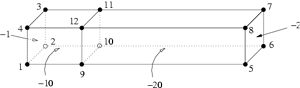
You can assign a boundary marker (an integer) for each facet of a PLC. In the final mesh, all boundary faces on that facet will have the same boundary marker. A common use of the boundary marker is to determine where boundary conditions should be applied to a finite element or finite volume mesh. Also You can assign different regions (separated by the internal facets) of the PLC with different region attributes (or number). Physically, they associate different materials to these regions. In the final mesh, All tetrahedra in the same region will have the same region number.
 |
 |
|
A bar with two boundary conditions defined (-1 on
the leftmost side and -2 on the rightmost side), and two region
attributes defined (-10 at the left part and -20 at the right
part). The TetGen input file is
bar2.poly
|
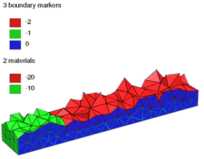
The quality mesh of the PLC on the left created by
command line switches "-pq1.414a0.1aA".
Boundary markers and region attributes are shown in different colors.
|
Adaptive mesh refinement
Adaptive mesh generation is important for many problems. For example, it helps to compute better solution at low CPU cost. The key for adaptive mesh generation is to refine the mesh at places where error is too large and to coare mesh at places where the mesh size is too dense. There are a number of ways to perform adaptive mesh generation in TetGen:
- You can impose tighter quality constraints by using -q with a smaller number, or -a followed by a smaller volume than you used to generate the mesh you are refining.
- You can create a .vol file, which specifies a maximum volume for each tetrahedra, and use the -a switch (without a number following). Each tetrahedron's volume constraint is applied to that tetrahedra.
- You can create a .node file, which contains a list of additional nodes that you want them to be in the mesh. Use -i switch to tell TetGen that you have an additional node list needs to be inserted.
- You can supply a nodal size map, which specifies the desired mesh edge size at each node. Use the -m switch to tell TetGen that a user-defined mesh sizing function is available. TetGen will then read the map and refine/coarse the mesh according this information.
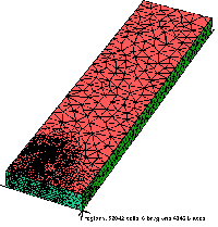
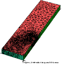
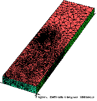
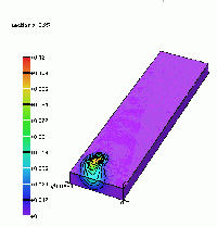
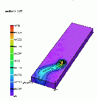
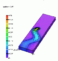
Below is an example of adaptive mesh generation for a heat conduction problem. The pictures show a sequence of mesh refined by using the -i switch and their corresponding solutions.
 |
 |
 |
 |
 |
 |
Mesh coarsening
Mesh coarsening removes existing mesh vertices therefore reduces the size of the mesh. It is useful in the adaptive mesh generation. TetGen provides two options for coarsening tetrahedral meshes:
- The user can select vertices to ratain or remove in the coarse mesh. TetGen will remove those vertices which are removable. This option is implemented by using the "pointmarker" list (i.e., the last colume in .node file), a '0' means "remove this point", otherwise, "keep it".
- The user can supply a mesh sizing function, let TetGen choose the point to remove, i.e., TetGen will remove the point if the mesh size at the point is too dense.
The new command line option for mesh coarsening is '-R'. It can be used either with '-p' (to coarse a CDT) or '-r' (to coarse a previously generated mesh). You can also use '-R' and '-q' together. TetGen will first perform mesh coarsening then do mesh refinement, hence the process must terminate and the mesh quality is improved.
Refine surface meshes
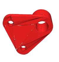
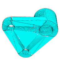
TetGen is able to remesh a surface triangulation into its constrained Delaunay triangulation or conforming Delaunay triangulation. This feature is helpful in the mesh refinement, which it will generally reduce the number of insertion point to enforce the mesh quality. An example is shown below.
 |
 |
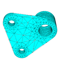 |
| The original surface mesh of a mechnical part, which has many skinny triangles | The remeshed surface mesh at the bottom. It is a constrained Delaunay triangulation of this facet. | The quality mesh of the mechnical part. Now the bottom part has been remeshed into a conforming Delaunay triangulation of this facet. |
Detect self-intersecting facets.
The inputs of TetGen are called piecewise linear complexes (PLCs). The definition of PLCs requires that they must be closed under taking intersections, that is two segments only can intersect at a shared point, two facets are either completely disjointed or intersecting only at shared segments or vertices, etc.
However, models created by most of the CAD tools usually do not satisfy this condition. TetGen can check and find out all the intersecting facets of the input PLCs and report in triangle pairs. This is done by using the switch '-d'.
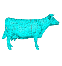
Below is an example shows how it works. The input is a surface mesh of a cow (cow.smesh) which has 2903 nodes and 5804 triangles. Using the command line:
tetgen -d cow.smesh
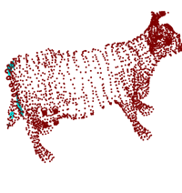
The detected intersecting facets are printed on the screen like followling:
Detecting intersecting facets.
  Facet #5672 intersects facet #5730 at triangles:
    (2872, 2874, 2873) and (2834, 2873, 2833)
  Facet #5726 intersects facet #5750 at triangles:
    (2872, 2873, 2834) and (2868, 2874, 2872)
  Facet #5730 intersects facet #5750 at triangles:
    (2834, 2873, 2833) and (2868, 2874, 2872)

  ...

  !! Found 211 pairs of faces are intersecting.

Intersection seconds:  3.33

Writing cow.1.node.
Writing cow.1.face.
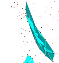
On completion, a list of intersecting triangles are saved in a .face file (i.e., cow.1.face).
 |
 |
 |
The surface mesh of a cow. |
The intersecting triangles. |
A closed view of some intersecting
triangles. |
This feature has another application: detecting two or more polyhedra are intersecting or not. You can describe these polyhedra in one of the file formats (.poly, .smesh, .off, .ply, .stl), then call TetGen with the -d switch only.
Read/write other polyhedral file formats (.off, .ply, .stl, etc)
In stead of reading and writting meshes in TetGen's own file formats, TetGen also supports other popular polyhedral and mesh file formats, such as OFF (Object File Format), PLY (Polygon File Format), and so on. This feature lets a large amount of free 3D models decribed in these file formats directly available for TetGen.
Currently, TetGen can directly read and write data in the following file formats: